What Is a Gear Coupling Types Working Principle and Selection Guide

Gear couplings are essential mechanical components in rotating equipment, designed to transmit torque between two shafts while accommodating minor misalignments. Unlike rigid couplings that require perfect shaft alignment, gear couplings provide the flexibility needed in real-world industrial installations where thermal expansion, foundation settling, and manufacturing tolerances create inevitable misalignment conditions.
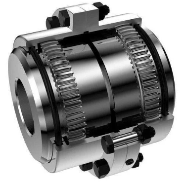
A gear coupling consists of two hubs with external gear teeth splined or keyed to each shaft, connected by a flanged sleeve with matching internal gear teeth. As the driving shaft rotates, torque transfers through the meshing gear teeth from the driving hub to the sleeve, then to the driven hub. The gear tooth design features barreled or crowned tooth flanks that allow angular and lateral movement between the hubs while maintaining full face contact for torque transmission.
Full Gear Coupling vs Half Gear Half Rigid Coupling
A full gear coupling has gear teeth on both hubs and accommodates both angular and parallel misalignment. This design is ideal for high-torque applications such as connecting a motor to a gearbox in heavy machinery, steel mill drives, and power generation equipment. The double-engagement design allows both shafts to move independently within the coupling’s misalignment limits without transferring bending moments to the connected equipment bearings.
A half gear half rigid coupling combines one geared hub with one rigid flanged hub. This design is used where one shaft position is fixed and the other requires misalignment accommodation. Typical applications include vertical pump shafts and certain marine propulsion systems where the gear half connects to the flexible component and the rigid half connects to a well-supported fixed shaft.
| Parameter | Full Gear Coupling | Half Gear Coupling |
|---|---|---|
| Misalignment Type | Angular + Parallel | Angular only (one side) |
| Torque Capacity | Very high (up to 12,500,000 Nm) | High |
| Axial Float | Both directions | One direction limited |
| Typical Application | Motor to gearbox, mill drives | Vertical pumps, fixed shafts |
The gear coupling size chart is the primary tool for selecting the correct coupling for your application. Selection starts by calculating the required torque capacity: multiply the system torque by an application service factor that accounts for load characteristics and operating conditions. For example, a 30 kW motor running at 1440 RPM produces approximately 203 Nm of torque, and a service factor of 1.5 for moderate shock loading brings the required rating to 305 Nm. The coupling selected from the size chart must have a torque rating equal to or greater than this calculated value.
For engineers working with existing equipment, the dimensions of both full gear coupling and half gear coupling types are available in standardized size charts. The charts typically list maximum bore diameters, pilot bore sizes, torque ratings, maximum RPM, and overall dimensions. Size 100 couplings accommodate bore diameters up to 35 mm with a torque rating of 50 kg·m, while size 119 couplings handle bore diameters up to 710 mm with torque ratings exceeding 149,000 kg·m. Always verify that the selected coupling’s maximum bore exceeds your shaft diameters by at least 3-5 mm to allow for keyway machining.